
¿Which Elements in a Mobile Network?
There are three mobile generations working simultaneously and, each one, with a different network elements. Obviously there are common elements allowing mobile users moving from one technology to another one even during a call. We will start with a simplified schema of a mobile network. it shows not all elements but the most important ones.
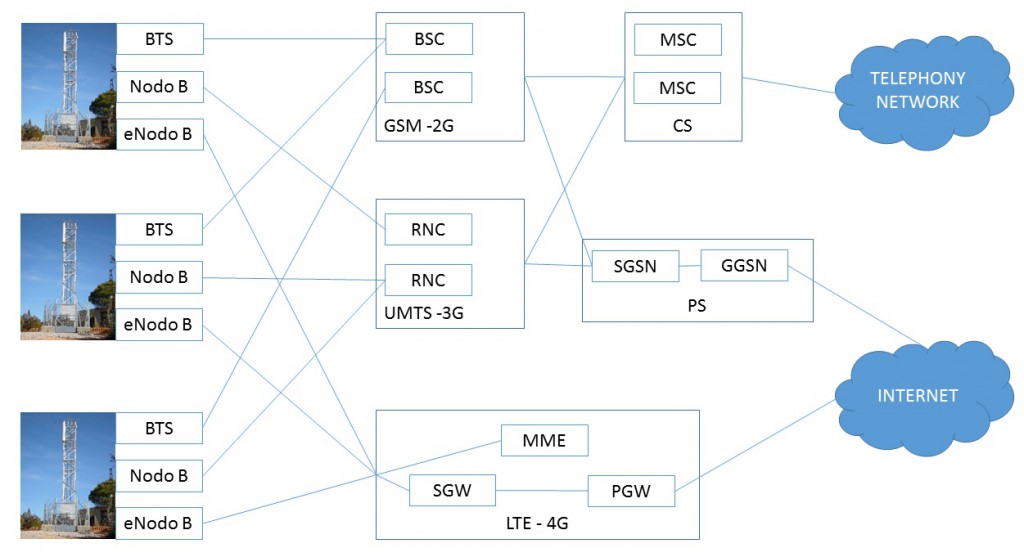
The first part more close to mobile users is the site including the tower, antennas in the top and the station in the ground where electronic equipments for different technologies are installed. Site is one of the most expensive element but not because of the electronic equipments. It is needed electricity supply and it used to be rented. Additionally are located in remote places making the maintenance difficult. This is the reason because the three technologies are deployed in the site as the extra cost is not too much. From this point every technology follow a different way.
![]()
![]()
![]()
GSM
GSM Network Architecture
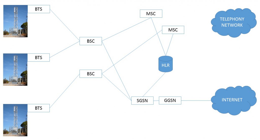
BTS
“Base Transceiver Station”. It is the element connected to GSM antennas. BTS is installed in a small building next to the tower in the site and it is connected through cables to the antenna in the top. BTS is connected to several antennas for the different cells of this site. Every antenna for every cell. BTS manage all the antennas/cells of the same site.
BSC
“Base Station Controller”. BSC manage all BTSs in a specific area. All BTSs in this area are connected to the BSC and their traffic flow through it. BSC controls all BTSs are working properly, manage BTS configuration and participate actively when a mobile user is moving from one BTS to another (hand-over). In 2.5 and 2.75 generations BSC split voice and data traffic following different ways from this point.
MSC
“Mobile Switching Center”. Communication exchanges managing voice calls in mobile networks. Not only BSCs but RNCs are connected to this element but this connection is only for voice ones. Data connections follow a different way. Technology used in MSC is the same used for fixed networks but the software is more complex as mobiles users are moving continuously and they could connect from any place.
HLR
“Home Location Register”. This network element store mobile users information. A new customer is setup in the network storing his information in corresponding HLR. HLR use to store information up to one million mobile users. All mobile network elements should know which HLR is the right one for each user. This mobile user information is static like telephone number, security parameters, diverts, services.
VLR
“Visitor Location Register”. It is a different logical element but phisically is part of MSC. VLR store dinamic mobile user information of the ones connnected to this MSC. VLR reduce the number of queries to HLR storing the necessary information of mobile users connected to correspoding MSC. Additionally has status and location information of them.
EIR
“Equipment Identification Register”. This element is not mandatory and it was not used at the beginning. EIR is used to verify mobile device identifier or IMEI (“International Mobile Equipment Identification”). All devices have a unique IMEI identifier. Mobile operator have our IMEI registered in their files if the mobile device is bought through it. Otherwise we should inform Mobile operator about our device IMEI. If our mobile device is stolen we could inform mobile operator and our device IMEI is included in EIR database. EIR have a black list and a grey list. If IMEI in black list device cannot be used even with a different SIM. If IMEI in the grey list device could be used but EIR send a warning. Stolen device IMEI is not only included in our mobile operator EIR. There are agreements between operators to exchange stolen devices IMEIs.
AuC
“Authetication Center”. This element is complementary to HLR. In order to maintain confidentiality in our communications and identify our device in the network in a secure way there are unique keys for each SIM. These security keys are stored only in the SIM and in AuC. There is no other place in the network storing these keys and AuC protect security keys confidentiality.
UMTS
UMTS Network Architecture
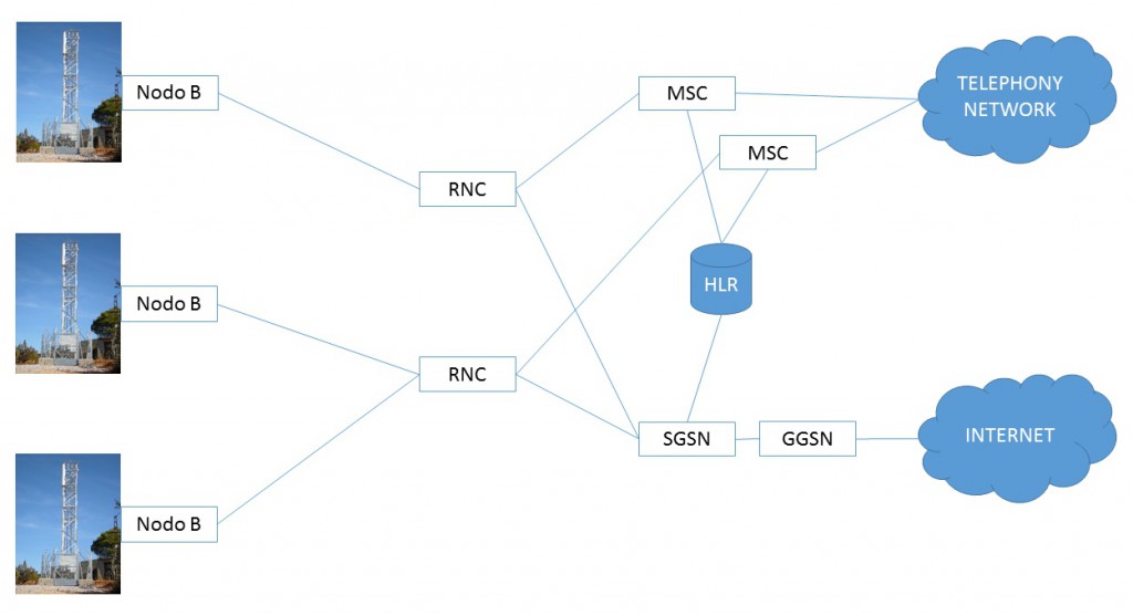
Node B
Node B is similar to BTS in UMTS network. Nodes B are equipments installed in the site connected to antennas sending and receiving 3G signal. Same than BTS a Node B manage all UMTS cells in the site.
RNC
“Radio Network Controller”. RNC is similar to BSC in UMTS network. ¿Why elements and names are different? 2G and 3G technologies are so different and network element functionality is so different as well. Anyway there is new concept called Single RAN combining 2G and 3G in a single controller doing BSC and RNC functionality. RNC split voice and data connections following different ways from this point.
SGSN
“Serving GPRS Support Node”. SGSN received data communications both from BSC and RNC. SGSN distribute data packets to the right GGSN and manage location and users in corresponding area. In case of roaming users SGSN send data packets to the home country GGSN. After 4G networks deployment SGSN communicate with new elements MME and SGW in order to facilitate fast transitions between 3G and 4G.
GGSN
“Gateway GPRS Support Node”. GGSN receives data communication from SGSNs. SGSN is associated to the area where mobile user are, even in other country, and GGSN is associated to the service provided and it is always in the our mobile operator network. GGSN is the end of mobile network and it connects to internet. From internet point of view mobile connections start in GGSN. All billing information and control are managed by this element.
LTE
LTE Network Architecture
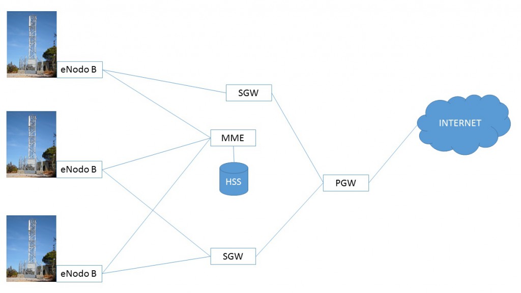
Above figure shows LTE network architecture. LTE network is more simple than previous technologies. It only considered data communication and it doesn’t support voice connections. Currently mobile device switch to 2G or 3G for voice connections but there is a new technology called VoLTE or Voice over LTE allowing voice calls over data connections. VoLTE is already available but not widely used.
eNode B
“Enhanced Node B” is the element installed in fourth generation sites. eNode B include some RNC functionality and it is not necessary any controller. eNode B use directly TCP/IP protocol (same than internet) but in a private network. Connections between eNode B and SGW are encripted to avoid any monitoring.
HSS
“Home Subscriber Server”. HSS is the evolution of HLR in LTE networks. HSS store (As well as HLR) static user data and active services. Currently mobile operators have separated HSS and HLR and it is necessary to update user information in both elements. In a short time HLR and HSS will share user database becoming two different interfaces of the same information.
MME
“Mobility Management Entity”. MME is the element managing LTE network. eNodes B don’t need a controller but sometimes it is needed a common element where eNode B request information about users or the rest of the network. MME provide user information (received from HSS) or select the right SGW for the connection. Connections with MME are only signalling ones and no data throughput is sent through this element.
SGW
“Serving Gateway”. SGW is the element receiving data communications from eNodes B. SGW isolate PGW from network mobility. When a mobile device is moving along the network there are a lot of data packets only to manage changes from one eNode B to another. SGW isolate all this management traffic not sent to PGW.
PGW
“Packet Data Network Gateway. PGW functionality is similar to GGSN one. PGW is the border between mobile network and internet. It assign IP addresses used by the users and, from internet point of view, all connections are starting in this element. Additionally PGW manage billing information and control.
Three previous elements (MME, SGW and PGW) are called EPC or “Evolved Packet Core”.